This page describes how to design a radio to work best with wfview. wfview is designed around the CI-V protocol, which is used by over a hundred existing radios. The CI-V protocol is simple, human-readable, and ideal for modern radios. A CI-V bus allows for multiple radios and computers on the same CI-V physical (or software) interface, and is thus ideal for the modern world of software controlled radios and networking. You can read more about the CI-V protocol here.
Connectivity
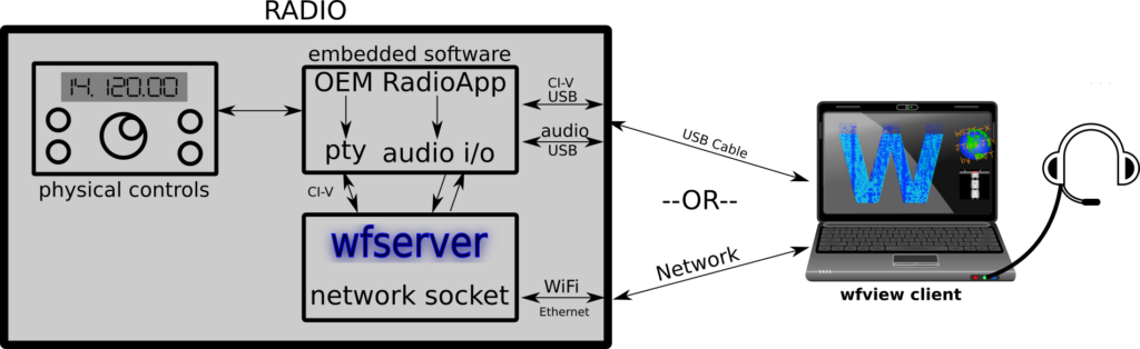
There are two primary methods wfview can connect to a radio.
- Using a USB port, which emulates a basic serial port
- Using a network connection (WiFi or Ethernet typically)
For network connections, wfserver can be run directly on the radio to serve the CI-V control and full-duplex audio over the network. wfserver needs a CI-V bus to connect to, typically a pseudo-port (“pty”) hosted on the device, and an audio device to use (or a loopback to an audio device). With these two things made available, running wfserver on the radio will permit network control from wfview and some other popular software programs.
Features to implement
wfview is built off a set of somewhat “classic” CI-V commands dating back to the 1980s. These commands were selected for the highest level of compatibility with the most radios on the market and compatibility with most software programs. Using this set of commands assures your radio can be pretty easily controlled, not just by wfview, but by many other programs.
One of the most popular and fun features to implement is of course spectrum output (waterfall). wfview can contend with any reasonable width of spectrum. Care must be taken not to exceed the bandwidth of the serial port. The exact details of the data are described below.
Please be sure to give the user a way to set the audio input to use the LAN audio versus the MIC audio. Without this selection the user does not know which audio source will be transmitted. Follow the example from other radios which provide this functionality.
Other features include frequency, mode, PTT, metering (S-meter, power, ALC, SWR, etc), Rig Identification, attenuators, preamp, mic gain, RF Gain, TX Power, Antenna switch, input mod source, etc.
The CI-V bus should fully support “CI-V Transceive” which means two principle things:
- The radio will respond to data sent to address “0x00” (“Broadcast”)
- This is how wfview and many other software programs “find” connected radios without making the user fill out CI-V address and model number data.
- The radio will, without a query command, send out changes to frequency and mode, when these changes occur from the radio’s physical controls (ie, a knob twist).
- This makes the radio and software connection much more responsive and up-to-date. wfview does not hammer the radio for information since the radio freely sends applicable changes over CI-V.
CI-V Transceive should be able to be disabled for legacy applications.
Command Set
The following tables show the expected command sets that are supported by wfview.
Common to all radios:
| Command Name | Core Syntax | Notes |
|---|---|---|
| Frequency | 0x00 | |
| Mode | 0x06 | |
| PTT | 0xC1 0x00 | |
| S-Meter | 0x15 0x02 | |
| Power Meter | 0x15 0x11 | |
| Rig ID | 0x19 | Important: Pick unique reply |
| Attenuator | 0x11 | |
| Preamp | 0x16 0x02 | |
| Mic Gain | 0x14 0x0B | Or: Copy IC-9700 level commands for MIC, USB, LAN |
| RF Gain (receive) | 0x14 0x02 | |
| TX Power | 0x14 0x0A | |
| Squelch | 0x14 0x03 |
Unique to each radio:
For these features, wfview has unique commands set up for popular radios. Please pick a popular and supported radio to “clone” these commands from rather than making your own set. The IC-9700, 7300, and 705 are great examples for these commands.
- Antenna Switch
- Input (MOD) source select (MIC, ACC, USB, LAN, etc)
- Modulation Level. Either just use the above mic gain for all, or, implement the full set from the IC-9700 for each of MIC, ACC, USB, and LAN, as applicable.
- Spectrum Data (see below)
Spectrum (waterfall) Data
Following in the footsteps of giants such as the IC-7300, radios should support sending spectrum data (“waterfall”) out at regular and automatic intervals. The IC-7300 spectrum commands are recommended as a baseline for any implementations.
Commands:
| Command Name | Command | Notes |
|---|---|---|
| Scope Data Prefix | 0x27 0x00 | actual scope data |
| Scope Data Output enable/disable | 0x27 0x11 | |
| Scope Mode (center, span, scroll) set/get | 0x27 0x15 | |
| Scope Span get/set | 0x27 0x15 | |
| Scope Edge get/set | 0x27 0x16 | |
| Scope Reference Level get/set | 0x27 0x19 | |
How the spectrum data is sent:
Spectrum data is sent one “line” at a time, which, when combined, form a waterfall display. Icom cuts these lines into smaller “chunks” for slower serial port links (11 chunks per line, to be exact), however this is not chiefly necessary for modern hardware. The spectrum data lines include the frequency range, either given as a +- “span” or as the start and end frequencies, depending on the mode. Spectrum amplitude is sent as numbers ranging from 0-200 (lower ranges are fine as well), with one bytes per pixel sent.
Typical data rates over network are around 30 lines per second. For USB connections, typical rates are 5-10 Hz.The messages are like this:
Start:
Main/Sub[00=main 01=sub] SequenceNumber[01-11] TotalSeqneuceSize[01=LAN, 11=USB]
For LAN radios, the next part is like this:
Center/Fixed [00=cent, 01=fixed]
Now it will send slightly different information depending on if we are in “center” or “fixed” mode:
Center:
CenterFreq[encoded like standard icom frequencies] Span [encoded similar to standard frequency encoding, see IC-9700 CI-V manual, page 24]
Fixed:
StartFrequency[encoded like standard icom frequencies] EndFrequency[encoded like standard icom frequencies]
Range information, to tell the user if they are out of the scope’s range somehow:
00 = In range, 01 = Out of range
Now waveform data. This is the data taken from the magnitude of the Fourier Transform, sometimes called the “FFT” data. The data are 475 points long (each “point” is basically a bin composed of a segment of the scope span). Each point may have values from 0 to 160 (0x00 to 0xA0). We believe these are logarithmic spaced, although I don’t know of anyone that has checked it.
For USB connections, it is very similar. The first “chunk” is a message with only the “information” about the scope settings (center/fixed, start/stop freq, span). The next 10 chunks are pieces of the 475 waveform bits. These 10 chunks include the Main/Sub, Sequence number (2 through 11), and of course the wave data.
New radio designs could send wider spectrum and also potentially use numbers a bit more than 200 for more dynamic range. wfview can easily adapt to changes such as these, provided the radio identifies itself in a way we can understand.
Example Spectrum Data
Here is an example of spectrum data from the IC-9700. The data are not split into chunks in this example:
27 00 00 01 01 00 30 99 19 44 01 00 00 25 00 00 00 0d 0c 00 06 04 08 04 00 00 08 10 0c 00 07 0a 05 07 06 00 00 00 00 09 07 0a 01 0c 00 0e 10 00 00 00 02 02 00 00 06 08 00 0f 14 08 02 00 03 00 00 00 1c 23 06 09 00 00 00 00 0c 09 05 00 00 00 04 04 08 02 07 03 0c 28 2c 13 09 00 01 02 00 00 03 05 07 05 04 03 06 10 0e 00 00 00 09 08 11 0f 03 03 00 00 00 00 00 0b 0e 09 0e 0c 0a 00 00 09 0a 00 00 02 00 09 0c 09 0e 0a 03 06 04 04 0b 03 07 01 00 00 02 00 00 08 00 05 07 07 02 0c 0c 10 10 08 00 04 00 12 0f 05 02 00 00 05 0b 06 00 00 01 0d 0b 04 03 00 05 04 0d 09 00 00 08 00 00 01 03 00 0b 0c 08 09 00 00 06 00 00 00 05 04 00 02 00 00 06 11 13 00 00 0f 0c 00 02 08 00 06 00 02 04 00 02 0d 11 00 00 00 00 00 00 05 0b 00 00 00 07 05 0e 0b 00 00 05 00 03 05 00 0a 08 00 00 00 00 00 06 04 00 12 19 0f 07 0a 06 0f 15 13 02 01 01 0e 00 0c 0d 07 04 00 09 09 06 00 02 02 00 00 07 0b 00 00 0d 05 02 00 00 00 00 04 08 00 06 05 00 01 07 0c 02 00 00 00 00 00 00 00 00 04 00 00 06 00 09 00 00 03 04 04 03 03 03 07 07 00 06 00 00 00 03 01 03 00 06 00 00 06 0a 00 00 01 07 08 00 0a 10 05 00 00 00 01 00 01 00 00 00 00 04 00 08 0d 07 02 04 05 06 0f 0f 08 00 00 00 07 03 00 04 00 11 0d 00 00 00 00 00 0b 0a 00 01 00 00 00 05 02 00 0e 0f 07 0a 00 02 00 00 00 00 03 10 0f 00 00 04 00 06 06 00 08 00 0b 06 00 02 00 00 02 0f 25 24 15 1c 0d 09 03 00 06 04 10 0f 0d 05 01 00 00 00 08 0b 06 08 00 00 00 00 00 00 06 07 07 00 00 04 07 04 06 09 08 05 00 00 00 00 04 00 00 08 00 0c 00 08 07 01 06 00 00 09 0b fd
Here is an example of spectrum data from the IC-7300, which is split into chunks:
Chunk #1 includes center/fixed mode at [05]. No pixels.
INDEX: 00 01 02 03 04 05 06 07 08 09 10 11 12 13 14 15 16 17
DATA: 27 00 00 01 11 01 00 00 00 14 00 00 00 35 14 00 00 fd
Chunks #2 to #10, which represent 50 pixels of spectrum data each:
INDEX: 00 01 02 03 04 05 06 07 08 09 10 11 12 13 14 15 16 17 18 19 20 21 22 23 24 25 26 27 28 29 30 31 32 33 34 35 36 37 38 39 40 41 42 43 44 45 46 47 48 49 50 51 52 53 54 55
DATA: 27 00 00 07 11 27 13 15 01 00 22 21 09 08 06 19 0e 20 23 25 2c 2d 17 27 29 16 14 1b 1b 21 27 1a 18 17 1e 21 1b 24 21 22 23 13 19 23 2f 2d 25 25 0a 0e 1e 20 1f 1a 0c fd
Note: Chunk number is identified at index 03, with the total number of chunks at index 04. In this example, chunk 7 out of 11 is indicated.
Chunk #11, final chunk, 25 pixels:
INDEX: 00 01 02 03 04 05 06 07 08 09 10 11 12 13 14 15 16 17 18 19 20 21 22 23 24 25 26 27 28 29 30
DATA: 27 00 00 11 11 0b 13 21 23 1a 1b 22 1e 1a 1d 13 21 1d 26 28 1f 19 1a 18 09 2c 2c 2c 1a 1b fd
As you can see, the “single piece” format used on the IC-9700 for network spectrum is much easier.
Licensing
wfserver is distributed under the GNU/GPL Version 3. This means that you may include it inside your radio provided that it is not modified, or, provided that any modifications to wfserver are made available to the end-user as source code. Most likely you will not need to modify wfserver any, and may simply use it as-is. If you find modifications are needed, please contact our team and we may actually make the modifications part of the standard wfserver (and thus relieve you of needing to distribute the source code), depending upon what has been changed.