wfview’s settings can be accessed by pressing the “Settings” button in the bottom-left corner of the main window.
On the left side of the Settings window, you will see several categories of settings:
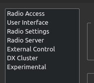
At the bottom of the Settings window, there are the following buttons:
![]()
Save Settings: Press this to save your settings
Revert to Default: Press to reset your settings. You can also start wfview with the command-line arguments --clearconfig CONFIRM
Connect to Radio: Press to connect to your radio (after it has been configured, of course)
Click on one of the following links to read about each of the settings pages:
Radio Access | User Interface | Radio Settings | Radio Server | External Control | DX Cluster | Experimental
Radio Access
These controls tell wfview how to access your radio:
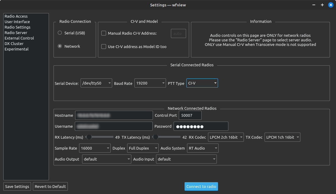
Radio Connection:
- Brand: Select Icom or Kenwood
- Serial (USB): Select this for radios that connect using a USB cable or a form of a serial port cable.
- Network: Select this for radios with built-in WiFi or Ethernet.
Generally, if a radio offers both USB and Networking, the networking connection will provide a better experience.
When Serial or Network is selected, various additional controls will be enabled.
Serial Connected Radios:
- Serial Device: Select the serial device here. Select “Auto” and wfview will use the first serial port it sees, which may be fine if there is only one such device. Select “Manual” to type in your own serial port. wfview should automatically populate the list of connected devices. Make sure you have permission to access the serial port.
- Baud Rate: The bit rate for the selected serial port. 19200 is common for modern CI-V radios, but older ones may be 9600 or even lower. Always try your radio’s highest supported baud rate first, and make sure to configure your radio prior to connecting. Some radios may need to restart after changing their baud rate.
- PTT Type:
- CI-V: Modern Icom radios (IC-7100, 7200, 7300) support commands which can be sent to set the PTT on and off.
- RTS and DTR: Older radios need a hardware PTT switch, and we can use the serial port’s DTR or RTS capability to signal PTT. If you have an adapter that supports hardware PTT, check carefully what signal is being used. NOTE: This is only for older radios (IC-718, for example). Do not use this option if your radio has a CI-V PTT command.
- Tip: Linux users can automatically set useful names for USB serial devices with reasonable default permissions. See this page on how to do it.
Network Connected Radios (WiFi or Ethernet):
- Hostname: Enter the hostname or IP address of your radio here. You can use the menus on the radio to see what its current IP address is (see the manual for the radio).
- Username: Enter your username as you have set it on the radio. Consult the radio’s manual for how to set up the username and password.
- Password: Enter your password as you have set it on the radio.
- Control Port: Enter the control port for the radio. The default is 50001. wfview will ask the radio for the other two ports.
- RX Latency: Sets the buffer size for the receive audio stream. Begin with a mid-range setting and increase it if you have audio dropouts. On a very good home network (LAN), you may be able to run this as low as 20ms. On a cellular data hotspot, try more like 300ms.
- TX Latency: Set the buffer size for the transmit audio stream. Generally it is recommended to monitor the RX audio stream and then adjust the TX Latency to the same value as a good RX Latency setting.
- RX Codec and TX Codec: Select the audio encoding scheme to use. The radio must support the selected stream. Use a 2ch (“stereo”) stream for radios that have dual VFOs (or if you are only using one VFO, use a 1ch stream. Kenwood users must use “LPCM 1Ch 16bit” or “ADPCM”. If you’re running your own radio server, you can select any format.
- LPCM: basic linear PCM encoding. 16 bit sounds a lot better than 8 bit. This is Kenwood’s “high quality” audio format.
- uLaw: an 8 bit format with enhanced dynamic range similar to approximately 14 bit linear PCM. Uses half the bandwidth of a 16 bit stream. Some VPN users may have better success with 8-bit streams due to packet mangling issues.
- Opus: Opus is a low-loss encoding scheme which delivers a very high quality audio stream with incredibly low bandwidth. This is recommended for users with low bandwidth connections, however, it is not supported by any Icom radios. The only situation where an Opus encoding can be used is when you are running your own radio server using another copy of wfview as the server. Opus uses only 10 KiB/sec and has some degree of forward error correction.
- ADPCM 1Ch: Kenwood’s “low quality” audio format.
- Sample Rate: Sets the sample rate for both audio streams. A 16 KHz sample rate will allow for audio up to approximately 8 KHz — plenty for even the widest of ham radio users.

The plot above shows the bandwidth used for a wfview connection to an IC-7300. The bandwidth includes scope data and other CI-V traffic. The plot below shows the bandwidth needed for the Kenwood 890, which also includes CAT (commands) traffic.

- Duplex:
- Full Duplex: Constantly stream audio for both transmit and receive streams
- Half Duplex: Mute the transmit audio when not transmitting, and mute the receive audio when not receiving.
- Audio System: wfview offers access to three audio systems. If one audio system gives you trouble, consider trying a different one. It is recommended to try the Qt Audio system first.
- Qt Audio: The default audio system which all Qt-based applications can access.
- Port Audio: An open-source audio API designed for high compatibility between operating systems
- RT Audio: An open-source audio API designed with real-time applications in mind.
- Audio Input: Select your computer’s microphone here. Or if you are using an external program such as fldigi or wsjt-x, select your audio loopback or virtual audio cables.
- Audio Output: Select your computer’s speakers or headphones here. Or if you are using an external program such as fldigi or wsjt-x, select your audio loopback or virtual audio cables. Don’t select the same cable as the audio input or you will get nasty bursts of feedback!
CI-V and Model (Icom only):
- Manual Radio CI-V Address: DO NOT set this parameter unless you have an absolutely ancient radio. Modern Icom radios have a feature called CI-V Transceive which, when enabled (please enable it), will cause the radio to self-identify to wfview.
- Use CI-V address as Model ID too: DO NOT set this parameter unless you have an absolutely ancient radio. This will cause wfview to assume that the CI-V address provided corresponds to a radio of the same default CI-V address.
- Please do not turn these parameters on unless you are absolutely sure you need to.
Once you have setup wfview for your radio, you can press “Connect to radio” to see if it works.
User Interface
These controls adjust how the wfview user interface appears and behaves.
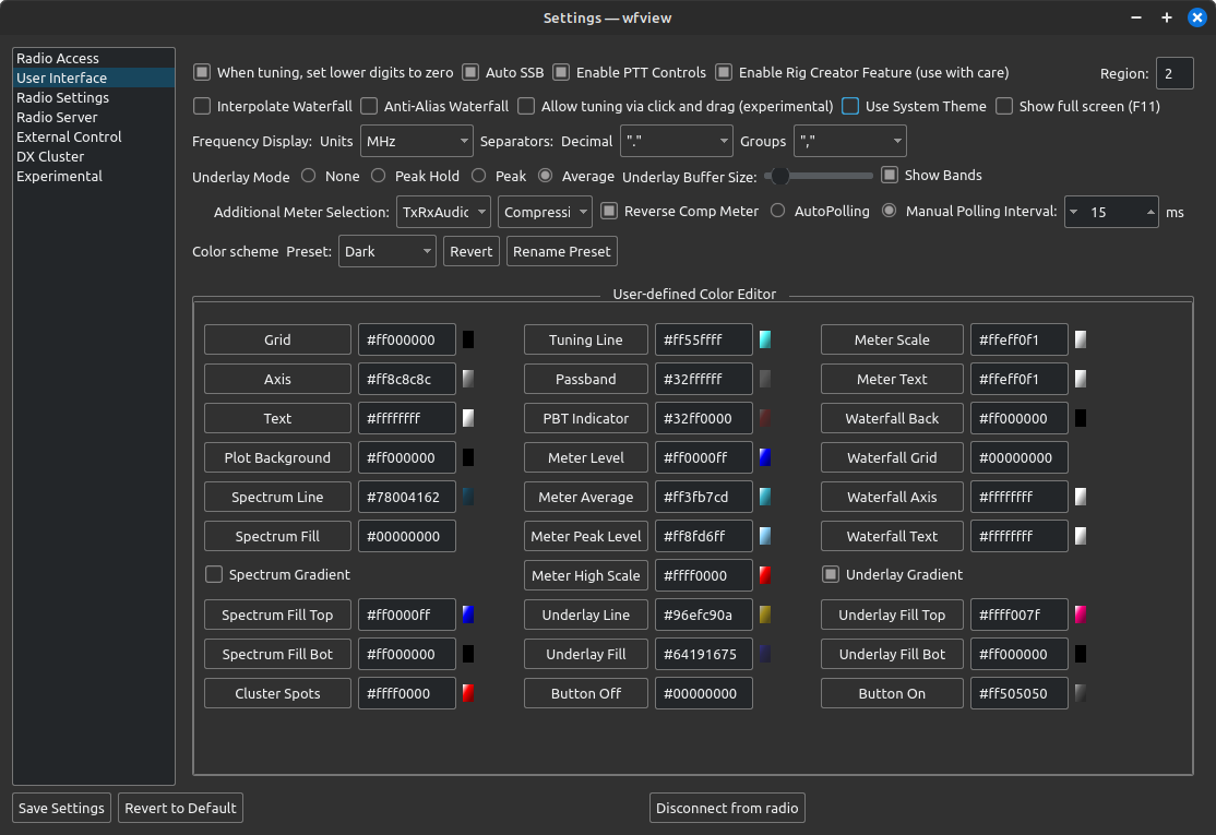
- When tuning, set lower digits to zero: This control causes the tuning dial to automatically set the below-tuning-step digits to zero. This is generally desired. Uncheck this control if you want to dial in and keep an offset applied to all your tuning, for example if you want frequencies always ending in 5 KHz for some reason.
- Auto SSB: This setting will automatically select the “correct” sideband when switching bands. This is only done if you are already in LSB or USB mode.
- Allow tuning via click and drag: This checkbox made it into the master branch accidentally. If enabled, you can try clicking and dragging on the spectrum to tune. It is an experimental option and still under development. Actually, it does not even work in V2.
- Interpolate Waterfall: If you have a big screen, check this box and the pixels of the waterfall will not look quite as blocky and pixelated. Checking this box can add significant CPU use, so do not do this on a humble platform like a Raspberry Pi.
- Anti-Alias Waterfall: Check this box for anti-aliasing on the waterfall display. This seems to have almost no impact on the performance or appearance! But it’s an option if you want it. There is some impact on CPU usage, so uncheck this if your computer is struggling to draw the waterfall.
- Use System Theme: Check this box to switch from wfview’s built-in theme (QDarkStyleSheet) to your desktop environment’s default appearance. Read more about this here.
- Show full screen: Check this box for full-screen mode. You can also use F11 to toggle full screen. Tip: For a dedicated wfview display, use a raspberry pi set to launch wfview on startup under the default user. Check the full screen box and save the settings.
- Underlay Mode: These four options select an “underlay” for the spectrum plot. The underlay is an additional plot shown under the radio’s spectrum data. Two of the underlay options obtain data from a variable-size buffer of received spectra, in which one value is deleted each time a new value is received. The size can be set using the buffer size slider. The available underlay options are:
- None: no underlay drawn
- Peak Hold: An underlay is drawn showing the maximum value received. The peaks do not expire except when tuning.
- Peak: A buffered peak mode. The peak value in the buffer (as set with the Buffer Size slider) is plotted for each frequency.
- Average: The average value for each frequency is plotted. This provides a “smoothed” spectrum mode which often helps beat down broad-band noise such as RFI.
- Underlay Buffer Size: Sets the size of the underlay buffer. Lower values will be more responsive, higher values will be more “sticky”. Tip: Press “Pop-Out” to see the effects of adjusting this slider in real-time as you make the adjustments.
- Frequency Display:
- Units: select the units desired for the frequency display. Generally, this is set to MHz.
- Separators: Select your desired decimal and group values. North American users will likely want to select “.” for the decimal and “,” for the group.
- Show Bands: Check this and wfview will show a line over the top of the spectrum indicating the amateur radio band. You can set the color of this display as well (it’s one of the color buttons below). For example, the 30M in this screenshot:

- Enable PTT Controls: Enables wfview’s transmit button. This checkbox has no effect on the radio’s physical PTT buttons, nor does it block any other radio control programs from sending PTT commands. It is designed to prevent inadvertent transmission, and could be useful during open radio demonstrations. wfview has a built-in 3 minute timeout on transmit.
- Secondary Meter Selection: Select a desired secondary meter here. Some radios do not support some meter types.
- Available meters: None, SWR, ALC, Compression, Voltage, Current, Center (IC-R8600 only), TxRxAudio (switches Tx/Rx automatically), RxAudio (RX audio all the time), TxAudio (TX audio all the time)
- See more about the meter under the View Tab manual page.
- Reverse Comp Meter: Check this box to draw the compression meter “broadcast-style” with reduction shown moving to the left as the reduction increases.
- Polling: wfview automatically determines the optimal polling rate for the radio. However, faster polling will make the meters more responsive and is generally fine so long as a secondary program isn’t polling as well. Slower polling rates may increase reliability, especially with older radios using single-wire CI-V. If you are running wfview as a server as well, it can make sense to set the polling period to a high value on the server so that the server isn’t contributing much to the overall polling activity. When set to Auto Polling, wfview may make adjustments to the polling time if the connection exhibits high latency. If you find this annoying, you can set the manual polling interval and it will not be adjusted. Be careful not to be too aggressive with the polling time. Typical polling times for network radios are around 20ms.
Color Scheme:
Use these controls to adjust the color scheme. Scoot the settings window over to the side so that you can see the UI change as you make adjustments. More information on customizing the appearance is available here.
- Preset: This control is for recalling the five available color scheme presets. Presets are saved with the settings and may be renamed and reverted.
- Save Preset: This button will save the selected preset’s colors and name to the settings file.
- Revert: Press this button to revert the selected preset to the default values.
- Rename Preset: Press here to rename the selected preset. Names may be up to ten characters long and may contain spaces and probably even unicode characters.
User-Defined Color Editor Buttons
Use these buttons to change the colors of many of the user-interface elements of wfview. The color editor allows a custom color to be selected. Simply press the button for a given attribute (such as “Grid”, “Axis”, “Text”, etc) and the color picker will be shown:
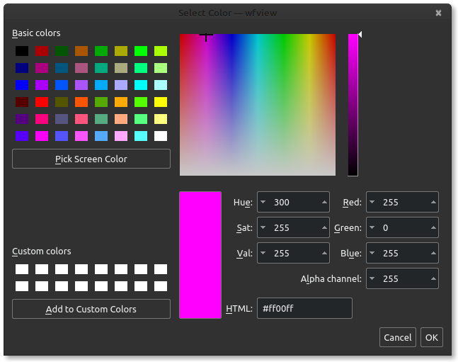
Alternatively, you may enter in HTML-style color codes. Keep in mind the first two characters represent the “alpha” channel. “ff” means opaque, and “00” means transparent, which is a nice way to turn off any distracting elements that you don’t wish to see (such as the grid lines on the waterfall).
Radio Settings
This settings page is a convenience feature to help you access frequently-used radio settings.

Modulation Source: wfview shows here the radio’s selection of available modulation (transmit) audio sources. For most people, you will want this set to “LAN” while you are using wfview, and set to “MIC” or “M/U” when not using wfview.Icom radios typically have a setting for “normal” data-off modes, and a setting for DATA modes (such as USB-D). “M/U” means “Mic/USB” and “M/A” means “Mic/Accessory”. Please refer to your Icom manual to see what this means.
Set Clock: For the IC-7300, this will set the clock to the computer’s clock. The actual clock is set when the seconds go to zero, since there is not a way to send the seconds in the command. So you may need to wait up to a minute for the command to complete.
- Use UTC: Set the radio’s clock to UTC
- Set radio time on connect: Set the radio’s clock every time you connect. This was a requested feature of a 7300 user that was tired of the tremendous clock drift present on the radio.
Manual PTT Toggle: Use these buttons if wfview is somehow confused about the PTT state and PTT Toggle is not working. Honestly, you won’t need it these days.
Radio Server
This settings page is for configuring wfview’s built-in radio server, which allows radios without built-in network connections to become accessible over the internet. For example, an IC-7300 can be connected with a USB port to a dedicated “server” computer and then connected to over the internet for remote use. This is an advanced feature for users already familiar with the concepts of computer networking.
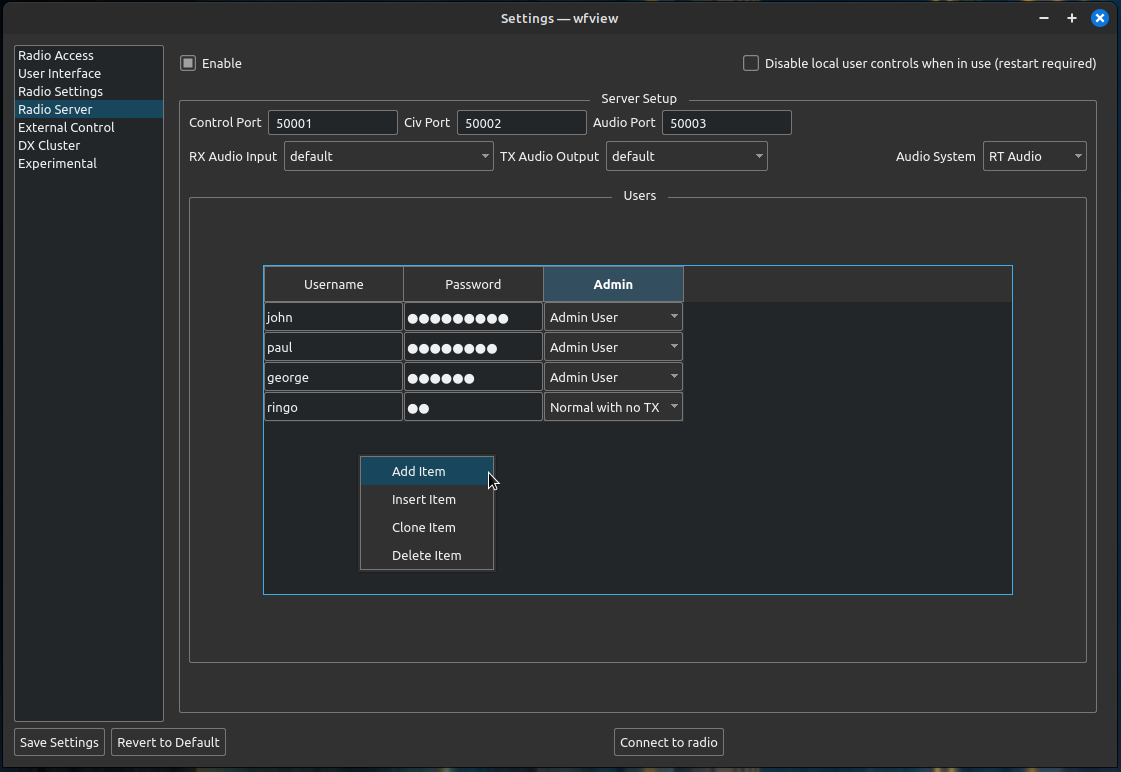
To enable the radio server, check the “Enable” box at the top.
To disable local control within this “server” wfview instance, check the “Disable local controls when in use (restart required)” box, and restart wfview once everything is set up as you want.
- Control Port: The port over which the remote session is managed. The default is 50001 and the protocol is UDP for Icom radios and TCP for Kenwood radios.
- Civ Port: The port used for CI-V commands. The default is 50002 and is UDP for Icom radios.
- Audio Port: the port for the audio streaming. The default is 50003 and is always UDP.
Audio settings: Very important. Be careful here and select your radio’s audio input and audio output:
- RX Audio Input: Select the radio’s receiver audio. This is the radio’s audio output and wfview’s audio input. Typically this will be “USB CODEC” or some similar name.
- TX Audio Output: Select the radio’s transmit audio. This is the radio’s audio input and wfview’s audio output. Typically this will be “USB CODEC” or similar.
See this page of the manual for more information about remote control.
External Control
These settings configure how external hardware and other programs can control and interact with wfview. Examples of other hardware include USB jog wheels for tuning and PTT buttons. Examples of external software control are programs like WSJT-X and fldigi.
External software control is covered in depth here. Please read it carefully, this topic is important and worth understanding for modern ham radio operators.
External hardware control is covered in depth here.
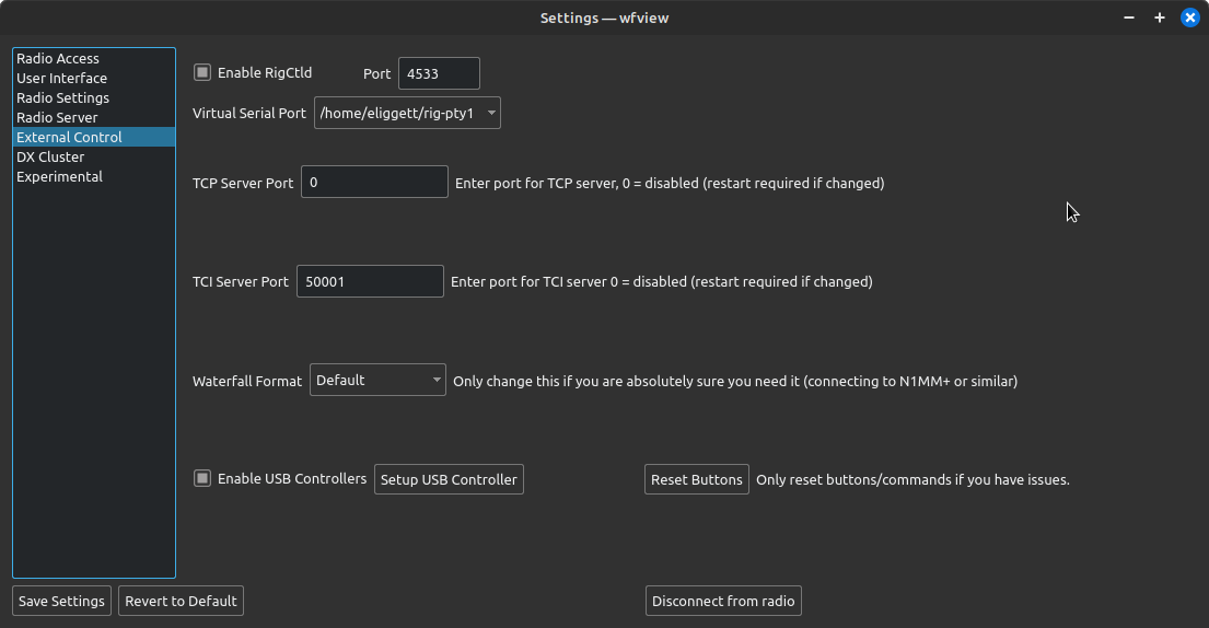
Enable RigCtld: Check this box to enable wfview’s built-in rigctld-compatible server. Don’t forget to make a note of the port. The standard port for rigctld is 4532; wfview defaults to 4533 so as to not conflict with any other instance of rigctld you may have running already (but really, you should not unless you have an unusual setup). Read more about this here.
Virtual Serial Port: Select a virtual serial port here which software can connect to which expects to connect directly to the radio. The virtual port will appear just like a serial port to the other application. Please read about this feature carefully here.
TCP Server Port: A raw TCP port which is similar to a virtual serial port. Used by N1MM+ and RUMLogNG
TCI: This is an advanced and rather experimental feature for sharing both audio and control with another application.
TCI Server Port: Set this to the port you wish to run the TCI server on. Set to zero to disable.
Waterfall Format: Use this feature to emulate LAN or USB-style waterfall data for external applications expecting the format of waterfall data to be different than what you have available. This is a rarely used option, and you should not use it unless you know you need it. Thus far only N1MM+ requires it, and only in some situations.
USB Controllers: There is a page on setting up USB Controllers here. There are many supported controllers, including the Icom RC-28. Press “Reset Buttons” if your button assignments are not working (possible after a major wfview version change).
DX Cluster
These controls are for setting up access to a DX Cluster. A DX Cluster is a server which provides users access to real-time dx reports. The callsigns of the reported stations are overlaid on top of the spectrum view.
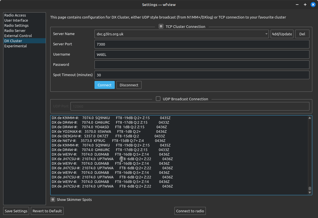
To add a DX Cluster server, either select it from the drop-down menu list, or simply type in the server and press “Add/Update”.
Supply the Server Port, Username, and Password. Many dx clusters do not require a password. Press Connect to use the cluster. Keep in mind it may be a few minutes before you see spots on the band you are currently using.
Set the Spot Timeout (minutes) to the amount of time after a spot is reported when the spot can be dropped from the display.
UDP Broadcast Connection: Enable this option to re-broadcast DX Cluster data to other programs.
Show Skimmer Spots: Show spots which have been “skimmed”
Here is an example of wfview showing DX Cluster results. The station’s reported frequency is on the left side of the drawn text.

Experimental
These settings are experimental and are not generally enabled. This category is used to briefly test features for developers only.