This section describes the main user interface of wfview
User Manual
Welcome to wfview
This is the official manual for wfview.
If you are just starting, please read the Getting Started chapter first. Most settings should be very intuitive, however, detailed explanations of each button and control are included in the links below.
For support, please visit https://forum.wfview.org/ and sign up.
First time guide
Once wfview has been downloaded, you will need to set up the radio and the program.
Radio Settings:
Set the radio to the default CI-V address. Enable CI-V Transceive.
For radios with ethernet or wifi: Set a known username and password, and enable Network Control. Make a note of the radio’s ip address.
For radios with Serial or USB: Set the baud rate to the highest supported rate, and make a note of the rate. Here is an in-depth guide to IC-7300 radio settings.
wfview settings:
First:
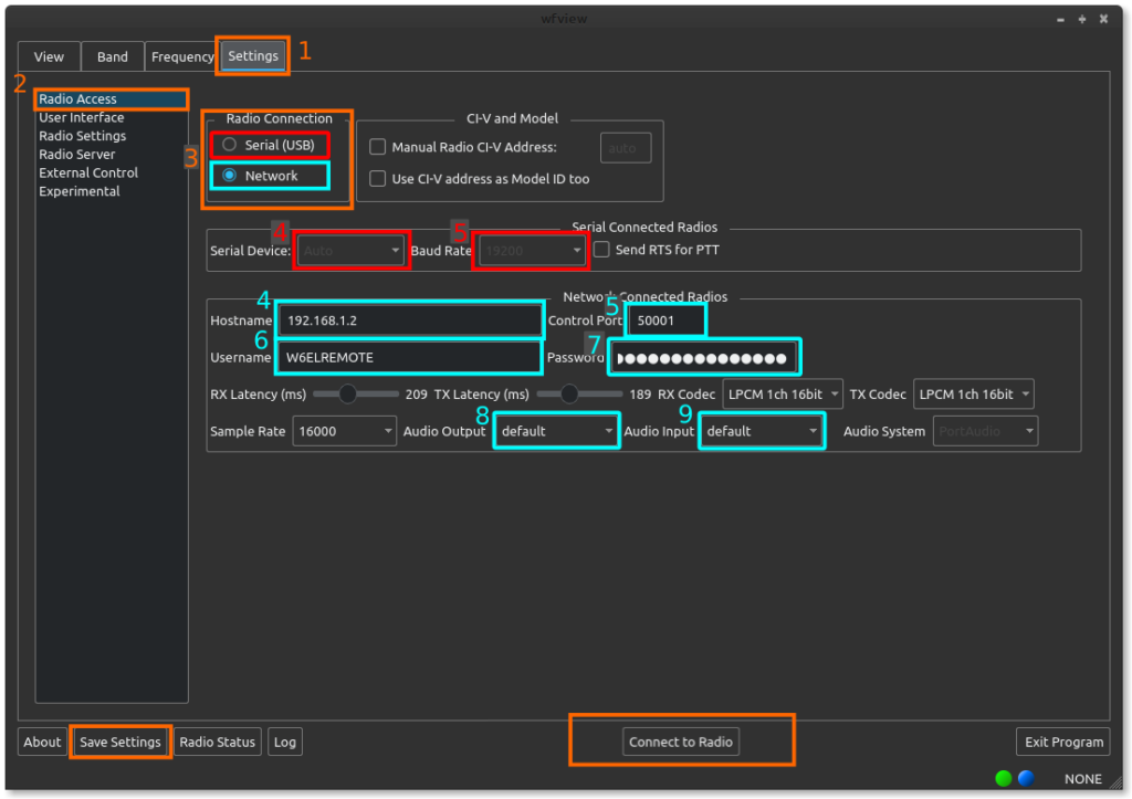
Press [1] “Settings” and then press [2] “Radio Access”. Select [3] either Serial (USB) or Network.
For Serial (USB) radios:
- Select the [4] Serial Device
- Select the [5] Baud Rate
- Do not manually set the CI-V address or Model ID unless your radio is quite vintage.
For Network (ethernet or wifi) radios:
- Type in the [4] IP address of the radio or radio server. If you know the hostname, you may supply the hostname instead.
- Enter the [5] Control Port. The default is 50001 on most radios.
- Enter the [6] username as set on the radio.
- Enter the [7] password
- Select the [8] audio output device you wish to use. Typically this is your headset or speakers. Linux users may simply select “default” for their desktop environment’s default audio choice.
- Select the [9] audio input device you wish to use. Typically this is your microphone. Linux users may simply select “default” for their desktop environment’s default audio choice.
Next, for both types:
Press “Connect to Radio” (bottom of the window). If successful, the radio model number should appear in the window title bar and the lower-right corner of the window. Once working, press “Save Settings” (bottom left of the window).
You can read the entire User Manual here.
FAQ
This is a collection of questions that we frequently see come up on the support forum. Please, have a look here before posting, it may save you a lot of time.
Jump to: Downloading/Installing | Audio | Waterfall | Sharing Control | Networking | Protocol
Section 1: Downloading, Installing, and Initial Run:
Q: I’m using Windows and I get an error that “MSVCP140.dll is not found.
A: This happens sometimes. Press “Ignore” if prompted. If there are errors running wfview, simply run the vcredist_x86.exe program, which is conveniently located in the wfview application directory (usually c:\program files (x86)\wfview\)
Q: I’m using Windows and I get an error that “VCRUNTIME140.DLL” is not found.
A: This happens sometimes. Press “Ignore” if prompted, and then simply run the vcredist_x86.exe program, which is conveniently located in the wfview application directory (usually c:\program files (x86)\wfview\)
Q: I’m using Windows and I get an error that “vcredist_x86.exe” failed to start or could not be found.
A: This happens sometimes. Press “Ignore” and then, if wfview will not start, simply run the vcredist_x86.exe program, which is conveniently located in the wfview application directory (usually c:\program files (x86)\wfview\)
Q: I’m using windows and I get an error that “Qt5Xml.dll” is not found.
A: This can happen if wfview isn’t in the same folder as that DLL file, and may especially occur since that is a new dependency found only in our daily and weekly builds. The DLL file can be found in our public builds folder. Simply place it in the same folder as wfview.exe and you should be good to go.
Q: I’m trying to use the latest public build and it is not working. It complains that it cannot find portaudio_x86.dll or qcustomplot2.dll (or some other DLL).
A: Any downloaded public build exe must go in the same folder as your existing wfview.exe. Do not rename any files, just move it to the same folder. If you are missing a DLL file, please check the public_builds folder to see if there are any DLL files that you need. Those DLL files need to go in the same folder as wfview.exe. When you have that set up, double-click on the new version of wfview that you downloaded, which will have a filename like “wfview-master-202323332.exe” or similar. Keep the original wfview.exe file around in case you wish to revert to the older version.
Q: I’m trying to use the latest public build and it is not working. It says “The application was unable to start correctly (0xc000007b)”.
A: Please make sure that you have all the DLLs from the public_build folder within the same folder as wfview.exe, which is also the same folder that you have placed the downloaded public build exe file. The error means that one (or more) DLL files is missing.
Q: I’m trying to run the linux build script and it says “permission denied” when I try to run the script.
A: Check the directions carefully. Make sure to add execute permission to the script: chmod 755 fullbuild-wfview.sh. Do not ever run the build script as root.
Q: I’m trying to run the linux build script and when I run it, it says “./fullbuild-wfview.sh: line 2: syntax error near unexpected token newline” (or similar)
A: Please follow the directions carefully. Most likely, you have inadvertently downloaded some HTML instead of the actual build script. When you click on the link for the script, you must then press the download button on gitlab’s web interface. This is also detailed in the video on linux install in our video section.
Q: How can I tell what version of wfview I have?
A: Press the About button.
Q: My wfview doesn’t look like the ones I see in screenshots or on youtube. Some features seem missing!
A: Please make sure you’re running the latest version. You can check using the About button, and compare with what is offered on our website.
Section 2: Audio
Q: I don’t have any audio on wfview client
A: Check your log (press “Log“) and see what audio device wfview is trying to use. Try disconnecting from the radio, changing the audio system, and then connecting again. You may also want to try other devices.
Q: The audio is distorted, too quiet, or too noisy
A: See if you can adjust the audio device gain in your operating system’s system preferences or control panel. Use wfview’s built-in “TxAudio” meter to view the audio level. Speaking should exceed -12dBfs, with some peaks over -6dBfs. Idle sound level should be below -30dBfs.
Q: The wfview log says “you may need to install libqt5multimedia5-plugins”
A: This only applies to some linux distributions, and the actual plugin name may vary. The error comes up when no audio devices are found. You may wish to try one of the other audio systems such as Port Audio or RT Audio.
Q: Why isn’t there any audio in wfview for my radio connected with USB?
A: wfview does not need to do anything with the audio from a USB radio, unless you are running a wfview server for remote access to your radio. If you need to access the radio’s audio, such as for a digital mode like WSJT-X or PSK31, simply select the radio’s USB audio directly from the digital mode program.
Q: (for network-accessed radios) Which audio device is my microphone? Which audio device is my speaker?
A: This is a tricky one. We present, in wfview, all the audio devices that the computer’s operating system and libraries expose. You may want to experiment with each device one by one, or even use another program to help you test your computer’s audio system carefully, so that you know what your devices are named. If you enable the TxAudio meter, it may help you with the microphone search.
Q: (for USB-connected radios, when running wfview as a server) Which audio device is my radio?
A: The exact name will depend a lot on the operating system. Windows often names the device “USB Audio CODEC”, and Linux may be similar or may even have “BurrBrown” in the name. If you see several, you may want to disconnect any and all USB audio devices and radios from the computer, close wfview, and then connect only the radio in question. Next, start wfview. If the list is still too cluttered, it can help to reboot with a minimum of audio devices connected.
Q: I picked up the mic on the radio and it isn’t transmitting any audio! What happened?
A: These days, radios have so many audio inputs for transmit (modulation). You can change the transmit modulation source to “MIC” using the menus on the radio, or conveniently, we have a menu in wfview which also performs this task on the Settings tab under the Radio Settings page. Simply set it to “MIC” for your radio’s microphone. You can read more about this here.
Q: When I connect to the radio over the network, nobody can hear me and I don’t see any transmit power indicated or ALC action.
A: Make sure you switch the radio’s Transmit Modulation Input to “LAN” so that the radio transmits network audio. You can do this either using the radio’s menus or using wfview’s Radio Settings page under the Settings tab. You can read more about this here. Additionally, make sure you have selected your computer’s microphone correctly under the “Radio Access” page of the Settings tab.
Section 3: Waterfall Display
Q: Which radios have waterfall display?
A: wfview gets the waterfall data from the radio. Therefore, only radios which provide waterfall data over CI-V will show a waterfall display in wfview. These radios are: IC-705, IC-7300, IC-7850/7851, IC-9700, and the IC-R8600.
Q: Why is the waterfall display so slow?
A: For a variety of reasons, when you use a serial or USB port for radio connection, the waterfall rate is quite limited. This is a limitation of the radio firmware; wfview displays the data as fast as it is presented over CI-V. Radios which support network connections (Ethernet or WiFi) will have significantly faster waterfall when you connect over the network instead of USB.
Q: I have a supported radio for waterfall but I do not see any waterfall.
A: The radio must be set at 115200 baud in order for it to generate waterfall data. Additionally, some setup menus must not be open on the radio’s screen, and the waterfall must be displayed on the radio display too. These are limitations baked into the firmware and we cannot change them. Please see our IC-7300 guide for complete setup information if you are having difficulty making this work. Additionally, if you change baud rates to 115200 (as required), you will need to cancel and/or disconnect with wfview and then re-connect when you change baud rate. This is simply a limitation of how serial ports are handled.
Q: Can I lower the CPU usage when drawing the waterfall?
A: Yes. Under Settings, on the User Interface page, disable Anti-Aliasing and disable Interpolation.
Q: Can I turn off the waterfall display:
A: Yes. There is a checkbox for this at the bottom of the waterfall display, “Enable WF”, which you can uncheck.
Q: Why is the waterfall so fuzzy?
A: Make sure to turn off Averaging and also set the Video Bandwidth Filter to “Narrow”. This will make a dramatic improvement in image sharpness.
Section 4: Sharing Control with Other Programs at the same time
Q: How do I run another program that controls the radio at the same time?
A: See this overview on the topic first. For programs supporting hamlib’s rigctld, use wfview’s built-in rigctld-compatible server. For programs without this support, use the built-in virtual serial port.
Q: How do I connect two programs at once to the virtual serial port?
A: That isn’t supported. The Virtual serial port can only connect to one program at a time. On the other hand, the rigctld server built-in to wfview can handle multiple connections at once.
Q: How do I get wfview’s client audio stream into another program?
A: You will need to create a loopback audio device. See this page for audio configuration.
Section 5: Display Issues
Q: The fonts all look too large
A: Check your operating system and see if you have any kind of Interface or Font Scaling enabled.
Q: How do I change the color of something in the plot? How do I make something disappear?
A: Go to Settings, and then click on the “User Interface” page. Use the color editor to select the desired colors. Setting a color to “#00000000” will make a given element invisible. More appearance notes are here.
Q: Where is the SWR/ALC/Audio meter? I see it in videos but I don’t see it in my wfview.
A: Look under Settings, and then click on the “User Interface” page. Make a “Secondary Meter Selection” to choose one of the other meters offered.
Section 6: Networking
Q: What is my ip address?
A: We don’t know. Every computer has a different method of showing your computer’s ip address. You may want to look in the control panels or system preferences. Remember, your computer’s ip address is not the same as your overall public ip address, which is assigned to your home router.
Q: What is my radio’s ip address?
A: We don’t know it. You can use the menus on the radio to find the ip address.
Q: I can’t connect to my radio or radio server
A: Please see if you can ping from your client computer to the radio or radio server. Please check that there isn’t a firewall on the client or server side that is preventing the connection (it may help to temporarily turn off any firewalls, just to eliminate this potential issue). Make sure the port numbers are correct. Make sure the username and password are correct. For Icom radios, make sure that network control is enabled in the radio’s menu. Check the log on both the server and the client side for potential error messages that could be helpful.
Section 6: Protocol
Q: What is the OEM networking protocol?
A: The networking protocol is quite complicated and it is not documented anywhere. wfview is open source software, and you can examine the source code if you want to see how it works. The protocol was first discovered by the kappanhag project. Additionally, this open source project, written in swift, has some good notes on the protocol. The wfview team regularly makes improvements to our implementation of the networking protocol, which is compatible with every available Icom radio with an ethernet or wifi connection to date. The protocol is complex and filled with subtleties which are difficult master, let alone describe. We would welcome help in this area though, since a proper description of the protocol would be helpful to everyone.
Contents of View tab
The View tab of wfview, also often called the “Main” tab, contains commonly-used controls for the radio and visualization.
Scroll down for a description of each element.
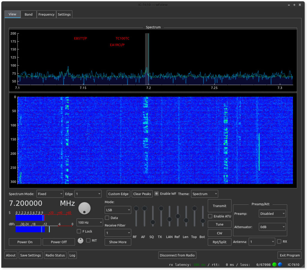
Spectrum plot and waterfall display:
These two items show the spectrum data passed from the radio to wfview. The vertical axis of the upper plot is likely proportionate to a value in dB, although the exact scale conversion isn’t known. Left to right is frequency. The bottom plot’s vertical axis is time, with newer values going in at the top. Many adjustments for these plots are available, read on to learn more.
Double-click anywhere in the plot to immediately jump frequency. A single click will simply show the frequency in the lower-left status bar area. Use the scroll wheel to quickly jog around the band.
The vertical tuning line in the upper plot indicates the carrier point of the radio. This is the frequency the dial indicates as well. The tuning line color can be customized (and even disabled via a transparent color) under the Settings tab on the User Interface page.
There is a divider between the upper plot and the lower waterfall section. You can drag the divider up and down to change the division of area between the plot and the waterfall.
Spectrum Mode and Edge controls:
- Spectrum Mode: This control selects between the radio’s built-in four modes: Center, Fixed, Scroll-C, and Scroll-F.
- Span: This control sets the total span for the spectrum, and is only available in Center and Scroll-C modes.
- Edge: In Fixed and Scroll-F modes, this control selects the current edge (1 through 4).
- Custom Edge: This button lets you define the scope edges in Fixed mode (in Scroll-F mode, the edge you define is translated over to the current frequency). The Custom Edge dialog box makes it very easy to jump to a desired frequency range.
- ToFixed: This button will take the current center span range and convert it into a fixed range. It is a quick way to keep the same displayed range and allow for tuning without changing the range displayed.
- Clear Peaks: Clears the spectrum underlay, which can be either Peak Hold, Buffered Peak Hold, or Average (select the desired mode under Settings).
- Enable WF: This checkbox can be used to turn off the waterfall data. This has the effect of freezing the waterfall display (good for taking a screenshot) and also makes the overall level of CI-V traffic a lot lower.
- Theme: Selects the data to color mapping scheme. The color themes come from QCustomPlot’s built-in themes, and can be seen here. Using the Top and Bot controls, the color scheme can be zoomed in around the data for very beautiful results.
Frequency and Tuning controls:
- Frequency: The current frequency is listed in large font (7.250 MHz). Tip: Press “*” (the star or asterisk key) to quickly jump to the Frequency tab and enter a new frequency).
- Knob: This is just a traditional tuning knob. You can use the scroll wheel of the mouse to turn it. Hold Shift or Control to increase the tuning step size.
- Tuning Step: This combo box (currently set at 100 Hz) sets the desired tuning step size. This tuning step is used for the tuning knob as well as scroll-wheel action over the spectrum and waterfall area.
- F Lock: This control locks the user interface tuning controls. It does not activate the radio’s tuning lock function, and will not stop external programs from tuning. Use this control if you want to prevent accidentally clicking or tuning around the spectrum
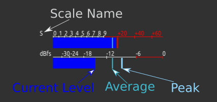
Meters:
wfview can display two meters at a time. The first meter is always power output during transmit, and receive strength (“S”) during receive. The second meter can be selected under the User Interface area of the Settings tab. Meters include: SWR, ALC, Compression, Voltage, Current, Center (IC-R8600 only), TxRxAudio, RxAudio, and TxAudio. Please keep in mind that the audio meters will only function for the client side of network radios. The audio meters do not do anything with a locally-connected USB radio.
The meter displays three numbers at a time.
- Instantaneous Level: This is the long solid bar which shows you the same value as the radio’s meter.
- Average: A thinner bright bar showing the average of the last ten or so readings.
- Peak: A thicker bright bar showing the maximum of the last ten or so readings.
The Meter Polling time can be adjusted under the User Interface page of the Settings tab. Shorter polling periods produce more responsive meters, but possibly at the expense of available CI-V bandwidth. wfview calculates a “safe” polling value on startup based on the type of radio connection, but faster values can be used if other programs are not polling as well.
Meter colors can be customized under the User Interface page of the Settings tab.
Power Controls:
On radios supporting this feature, the radio power may be turned on and off. Supported radios usually maintain some standby power which allows the radio to be remotely turned back on. For these radios, wfview may appear unresponsive on initial connection if the radio is off; pressing Power On will alleviate this condition. wfview will pause all communication to the radio for about three seconds during power on.
Mode and Filter Controls:
The mode may be selected from the pop-down combo menu (LSB currently in this screenshot). Some common modes may be quickly selected using keystrokes. The “Data” checkbox sets the data mode on the radio, for example, USB-D. Not all modes have a data mode.
The Receive Filter combo box allows for one of the radio’s existing filter definitions to be selected.
Show More opens additional radio controls such as IF-Shift. Not all radios support these controls:
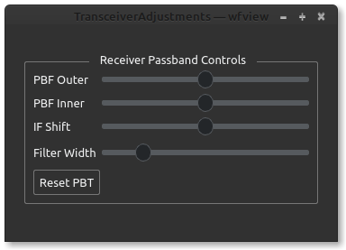
Use the PBF to shift the twin Pass Band Filter. The spectrum display will show the resulting adjustments to the PBF in red. Adjustments to the Filter Width will be in a lighter color. The IF Shift control can be used to simultaneously adjust both PBFs, simulating an IF Shift control.
Sliders:
The sliders in wfview are used as knobs for many common adjustments. The short names were chosen so as to allow the knobs to occupy less space in the interface. Each knob has useful “tooltip” text that can be seen by hovering the mouse over the slider for a few seconds. The numerical value of each slider is read out in the status text area (lower-left corner of wfview).
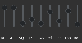
- RF: This is the receive RF Gain
- AF: This is the receive audio level. For network-connected radios, this is the volume of the streaming audio. For serial (USB)-connected radios, this controls the volume of the radio’s speaker. The level is saved when you save settings.
- SQ: Squelch. If you don’t hear anything on FM, try lowering this slider :-).
- TX: Transmit Power Level.
- MIC/LAN/USB/ACC/UNK: This next slider will have a name based on the currently-selected transmit mod (audio) source. For network radios, this will likely be set to LAN, and for serial radios being served onto a network using wfview’s built-in server, this will likely be set to “USB”, indicating the use of the USB port. MIC indicates the microphone jack, ACC is the accessory input, and “UNK” indicates an unknown setting, generally one of the “dual” settings that some radios support such as MIC/ACC. You can pick the radio mod source under Settings on the Radio Settings page. If you can’t transmit any audio, check here to see what the radio is set for, and adjust the level. It is a good strategy to verify audio by setting the meter to “TxAudio”. Once audio levels are verified, set the meter to ALC and adjust the LAN slider until you see appropriate ALC action. Some radios may have additional level controls available in the radio menu.
- Ref: This is the so-called Scope Reference Level. It is actually just a level control, but anyway, this lets you set the level of spectrum data.
- Len: This is the length of the waterfall display. Set to short values, you can see a lot of details, and set to long values, a longer history. This value can be changed any time; the waterfall data is always buffered for the last 1024 lines of spectrum.
- Top: This control adjusts the ceiling of the spectrum plot and the top value for the color mapping of the waterfall. Generally this should be set to match the maximum value on the plot. Set lower will accentuate the lower signals.
- Bot: This control adjusts the floor of the spectrum plot and the bottom value of the color mapping of the waterfall. Generally this should be set to just a little bit below the noise floor, although higher values will create a higher contrast display of strong signals.
Transmit, Tuner, and Repeater Controls:
- Transmit: Causes the radio to transmit. Control-T and Control-R can also toggle this behavior. PTT lockout is available under Settings on the User Interface page, titled “Enable PTT Controls”. While transmitting, this control will say “Receive”
- Enable ATU: This checkbox enables the radio’s automatic antenna tuner. If the ATU fails to tuner, this will automatically uncheck.
- Tune: This button causes the ATU to tune. Tuning success (or failure) will be indicated in wfview’s status text area at the lower-left.
- CW: Opens the CW Sender. See here for more information on the CW Sender.
- Repeater: Opens the Repeater Access Controls dialog box, where the tone, tone squelch, DPL, and repeater split direction can be set. Tip: Use the scroll wheel on the PL tone squelch combo box to quickly cycle through tones and find the repeater’s output tone. See here for more information on split and repeater usage.
Preamp, Attenuator, and Antenna Controls:
- Preamp: Select from the radio’s available receive preamps
- Attenuator: Select from the radio’s available receive attenuators.
- Antenna: Select from the radio’s available antennas.
- RX: Select the receive-only antenna (if available)
Bottom-Row Buttons (available in every tab):
- About: Brings up the about box, which displays the current version, git commit revision, and built date.
- Save Settings: Saves the current settings. Settings are otherwise discarded on exit.
- Radio Status: Shows the current radio and course audio levels. Future version of wfview may allow for multiple radios!
- Log: Displays wfview’s internal message log. This is generally the same text as the logfile. If wfview is not behaving as expected, click here and view the log. Read more about this feature here.
- Connect/Cancel/Disconnect: This button will connect to the radio, disconnect from the radio, or cancel an existing radio connection attempt. Look here to see if you have connected to the radio.
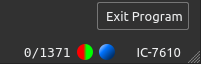
Bottom-Row Text:
- Left side: Status text. Shows slider values during adjustment and other information
- rx latency: latency for receive audio.
- rtt: round-trip time for receive audio
- loss: lost packets / total packets. For example, 0/25332 indicates that zero packets have been lost out of 25332 sent.
- Color “LEDs”: Green/Red LED indicates transmit and receive. I honestly forgot what the blue one means.
- NONE or Radio name: This text begins as “NONE” and changes to indicate the radio model number, for example “IC-718”. If you see “NONE” here, then your radio model is not being identified, possibly indicating a CI-V issue such as CI-V Transceive being off (it needs to be on) or other problems.
CW Sender
wfview has a built-in CW Sender which uses the radio’s built-in keyer. Text typed in by the user is sent to the radio for keying. A sidetone is not provided at this time, although it is possible to stream the sidetone from USB-connected radios (such as the IC-7300) when used with wfview as a server.
Note: The radio will not actually transmit any CW unless it is in CW or CW-R mode.
CW Sender Controls:
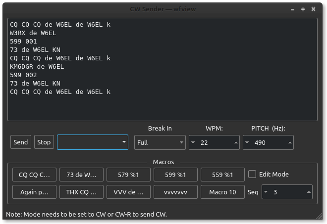
Top level controls as they appear:
- Send: This button sends the user text to the radio. In Full or Semi-Breakin mode, the radio will transmit and begin sending the CW.
- Stop: This button causes the radio to stop sending prior to actually finishing whatever text has been buffered from the user. Otherwise, stopping is automatic.
- The text box allows users to enter text to be sent to the radio. Up to 30 characters may be sent at once. Multiple stanzas of 30 characters may be sent to the radio, which will be sent out in the order they are received. Some characters are not allowed; check the log if you think your characters may be being sent oddly. Characters that aren’t allowed get replaced with a “?”.
- Break In: This combo box lets you pick the break In mode:
- Full: The transceiver will switch T/R in between words whenever there is a gap. Some amplifiers may not be able to keep up!
- Semi: The transceiver will transmit at the beginning of the CW stanza and receive at the end of all the buffered text.
- Manual: You, the user, must press Transmit at the beginning and press Receive at the end. The radio starts “sending” the CW immediately, so press Transmit quickly!
- WPM: Words per minute. The radio will accept 6 to 48 WPM.
- Pitch: The desired CW pitch, referenced to the tuned carrier frequency.
Macros
wfview provides ten user-defined macros for common phrases. The macros are saved when the user presses “Save Settings”. Macros may be edited by pressing “Edit Mode” and then clicking on a macro button.
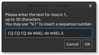
You can type in “%1” (without the quotes) to have wfview automatically replace the %1 with the current sequence number (otherwise referred to as a “serial” number). This is useful in some contests.
The sequence number may be changed using the up and down spinbox to the right labeled “Seq”.
Uncheck the “Edit Mode” checkbox to use the macros. Simply click a macro button to send it over the air.
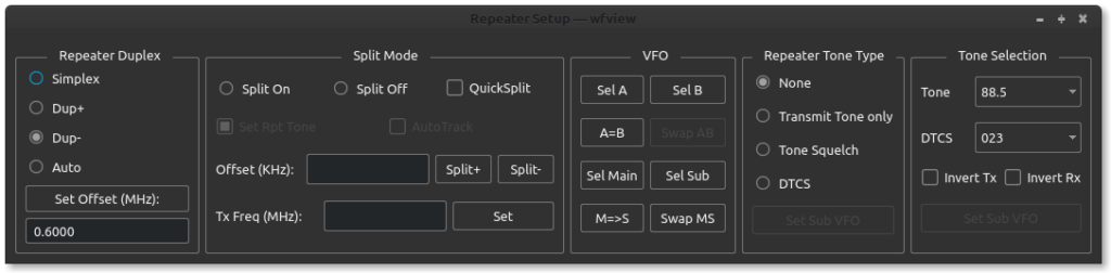
Repeater and split
This page describes how to use the SPLIT and Repeater settings of the radio. Press the “Rpt/Split” button in wfview to bring up this window:
Note: When transmitting with split enabled, the transmit indicator “LED” will have a split appearance:
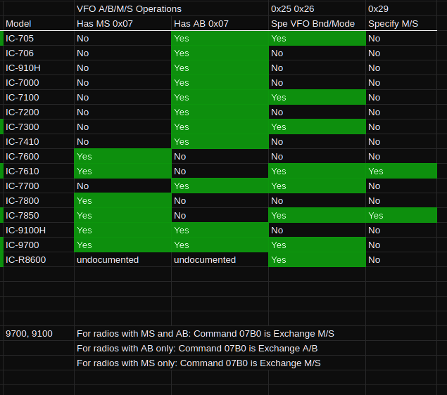
Supported Features
What you see in this window will reflect the features the radio supports. For example, most HF radios do not support the “Repeater Duplex” section but do support using Split Mode. Some radios support Main and Sub VFOs, and some support A and B VFOs. Additionally, exactly how some features on the sub VFO are addressed varies quite a bit. The IC-7610 and IC-7850 have special commands to allow the repeater tone to be set on the sub VFO; the other radios lack these commands.
Repeater Duplex
This section deals with repeater controls, primarily present on radios for accessing VHF and UHF FM repeaters.
- Simplex: transmit and receive frequencies are the same
- Dup+: The transmit frequency is above the receive frequency
- Dup-: The transmit frequency is below the receive frequency
- Auto: The radio should automatically decide which duplex mode to use (may not work correctly depending on your region)
- Set Offset (MHz): Type in the desired offset, in MHz, and press this button to set the default repeater offset for the currently selected band (ie, 2M/70CM/23CM)
Split Mode
This area handles split operation, available on most HF rigs and some VHF/UHF/SHF rigs
- Split On: Turns on the split feature, disabling any other duplex or repeater mode selected
- Split Off: Turns off the split feature. Some radios have both “split off” and “simplex” modes, but I can’t tell you what the difference is.
- Quick Split: Activate the radio’s quick split feature, when available. This feature is supposed to sync the repeater tone, mode, and frequency of the sub VFO. However, it can be “canceled” if the user makes certain adjustments to the sub VFO. The checkbox is available but you may need to experiment with it.
- Offset (KHz): Type in the desired split offset here, for example, 100 for 10M FM repeaters.
- Split+ and Split- buttons: These buttons set the radio’s secondary VFO (“B” or “Sub” depending upon the radio) to the appropriate split frequency and populate the Tx Freq box as a convenience to the operator. If the “Set Rpt Tone” checkbox is checked, and the radio supports such commands (7850 and 7610), then the secondary VFO’s repeater tone and tone mode is also set at this time.
- Tx Freq (MHz): You can manually type in a transmit frequency here and press “Set” any time. But it is not needed when using the Split+ and Split- buttons
- AutoTrack: Checking this box causes the sub VFO to automatically track the Main or “A” VFO with supplied Offset. In FM mode, the repeater tone and repeater tone mode will also track. Use this feature to discover 10M repeaters easily. As this function is similar to Quick Split, do not use both at the same time.
VFO Buttons
These buttons are for selecting, swapping, and equalizing VFOs.
- Sel A, Sel B, Sel Main, and Sel Sub: These buttons “select” a given VFO. On the radios I have, this is the same as touching the given VFO on the screen and does not provide much functionality. But it may be different on other radios.
- A=B: Sets the B VFO to the contents of the A VFO
- M=>S: Sets the Sub VFO to the contents of the Main VFO
- Swap A/B and Swap M/S: Swaps the contents of the two VFOs. Use this feature to rapidly swap between VFOs and to make adjustments to the Sub VFO when needed, for example, with radios that do not support addressing the SUB VFO directly and if you need to set a repeater tone.
I realize some of this seems incomplete or difficult to understand. I recommend playing with these features first with the radio at your side.
Repeater Tone Type
These buttons select the method of repeater tone access.
- None: There is no transmitted tone of any sort and there is not a tone squelch.
- Transmit Tone Only: A subaudable tone is transmitted. No tone squelch.
- Tone Squelch: A tone is transmitted, and the same tone frequency is used as a tone squelch.
- DTCS: Also known as DCS, a digital code is sent with your transmission and is also used as a digital tone squelch.
- Set Sub VFO: Available on the IC-7610 and IC-7850. Use this button to force the sub VFO to a specific tone mode (typically “Transmit Tone only”). This button’s function is automatically run when the “Set Rpt Tone” checkbox is checked.
Tone Selection
Use these controls to select a Tone and/or D(T)CS code. For D(T)CS, the Transmit and Receive code can be inverted.
Press “Set Sub VFO” to force the sub VFO to the specified tone selected. Not available on most radios and not available for D(T)CS. This button’s function is automatically called when setting split and the “Set Rpt Tone” checkbox is selected.
Radios and Features
For the curious, here’s a short chart on what features are available on what radios: